-
 AARONIA AG
-
 ADASH
ADASH
-
 Amptek
-
 AOiP
AOiP
-
 AstroNova
-
 Automatic Research
-
 AWSensors
-
 BASI
BASI
-
 BRS
BRS
-
 CALMET
-
 CHECKLINE
-
 Cmc
Cmc
-
 C-Tech
-
 CTRL
CTRL
-
 DANATRONICS
-
 DV Power
-
 EA Technology
-
 ECH
ECH
-
 EL-CELL
-
 Electrothermal
-
 Elsys
Elsys
-
 ELVEFLOW
-
 Enapter
-
 ENERGY SUPPORT
-
 Enervac
-
 FASTEC
-
 Gaskatel
-
 GE
GE
-
 GIUSSANI
-
 Globecore
-
 GMW
GMW
-
 GREENLIGHT
-
 GRZ
GRZ
-
 HIGH SENSE SOLUTIONSHTW
-
 HTW
HTW
-
 HUBER
HUBER
-
 HVPD
HVPD
-
 Ida
Ida
-
 Instytut Fotonowy
-
 IVIUM
IVIUM
-
 Jacomex
-
 Jenway
-
 JGG
JGG
-
 KEHUA TECH
-
 Labdex
-
 Labnics
-
 LIQUID
-
 METERTEST
-
 Metrel
-
 Microrad
-
 micrux
-
 ndb
ndb
-
 Neware
-
 Norecs
-
 Novocontrol
-
 OKOndt Group
-
 OZM
OZM
-
 Pine Research
-
 Redoxme
-
 SATIR
SATIR
-
 SDT
SDT
-
 Serstech
-
 VacCoat
-
 Zurich
- AARONIA AG
- ADASH
- Amptek
- AOiP
- AstroNova
- Automatic Research
- AWSensors
- BASI
- BRS
- CALMET
- CHECKLINE
- Cmc
- C-Tech
- CTRL
- DANATRONICS
- DV Power
- EA Technology
- ECH
- EL-CELL
- Electrothermal
- Elsys
- ELVEFLOW
- Enapter
- ENERGY SUPPORT
- Enervac
- FASTEC
- Gaskatel
- GE
- GIUSSANI
- Globecore
- GMW
- GREENLIGHT
- GRZ
- HIGH SENSE SOLUTIONSHTW
- HTW
- HUBER
- HVPD
- Ida
- Instytut Fotonowy
- IVIUM
- Jacomex
- Jenway
- JGG
- KEHUA TECH
- Labdex
- Labnics
- LIQUID
- METERTEST
- Metrel
- Microrad
- micrux
- ndb
- Neware
- Norecs
- Novocontrol
- OKOndt Group
- OZM
- Pine Research
- Redoxme
- SATIR
- SDT
- Serstech
- VacCoat
- Zurich
PAT-Tester-x-8
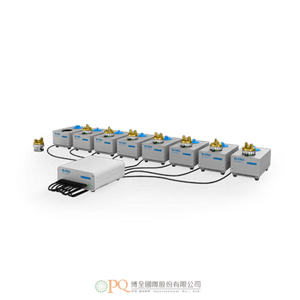
PAT-Tester-x-8 型號:PAT-Tester-x-8The PAT-Tester-x-8 potentiostat offers maximum flexibility with up to 8 channels for small scale and special purpose testing.
- Up to 8 independent channels for PAT-series and other test cells
- Each channel with fully featured potentiostat / galvanostat /
- impedance analyzer
-
Fully featured potentiostat / galvanostat / impedance analyzer with up to 8 channels for small scale and special purpose testing.
The individual test solution
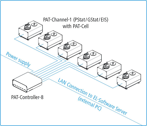
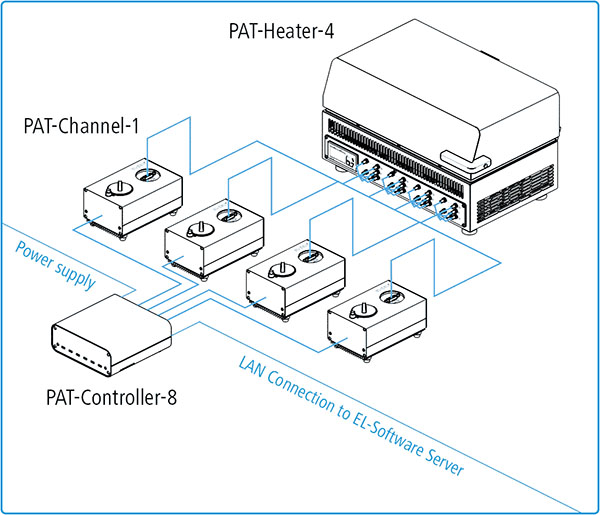
The PAT-Tester-x-8 is the perfect choice for small scale and special purpose testing. It brings the same battery tester hardware and software as the PAT-Tester-i-16. However the test channels are separated into individual devices, the so-called PAT-Channel-1. Each PAT-Channel-1 features a fully equipped galvanostat / potentiostat / impedance analyzer. Up to 8 PAT-Channels may connect to one single PAT-Controller-8 which serves as the control unit for storing all measurement data and enabling communication with the EL-Software server. That way each channel of the PAT-Tester-x-8 can be controlled from any client PC in the same network via EL-Software.
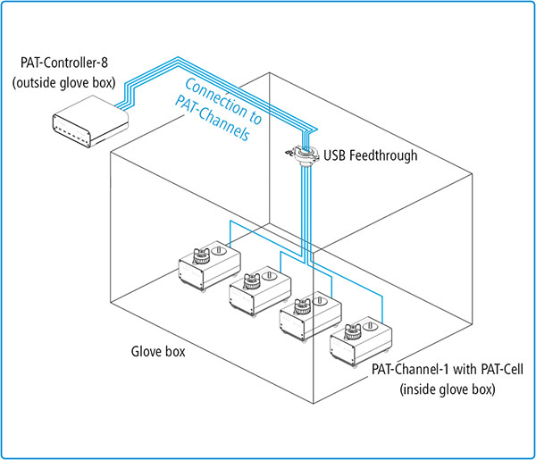
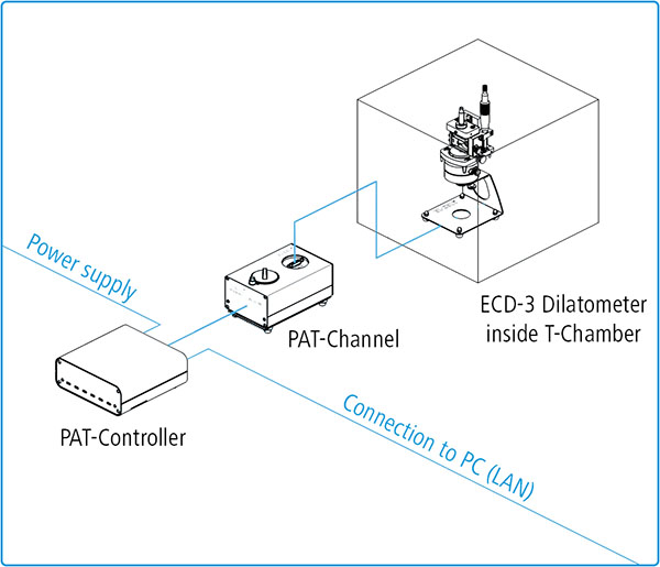
The individual PAT-Channels can be placed where they are needed: on the bench, in a climate chamber, or even inside the glove box. While tailored for PAT-Cells, each PAT-Channel-1 can also connect to almost any other test cell including the ECD dilatometer, optical ECC in-situ cells and all other small format cell (e.g. coin cells, pouch cells, T-cells).PAT-Tester-x-8 setup with 6 PAT-Channels
PAT-Tester-x-8 setup with 4 PAT-Channels inside the glove box
Single-channel setup with ECD-3 Dilatometer
PAT-Tester-x-8 setup with 4 PAT-Channels and PAT-Heater-4
-
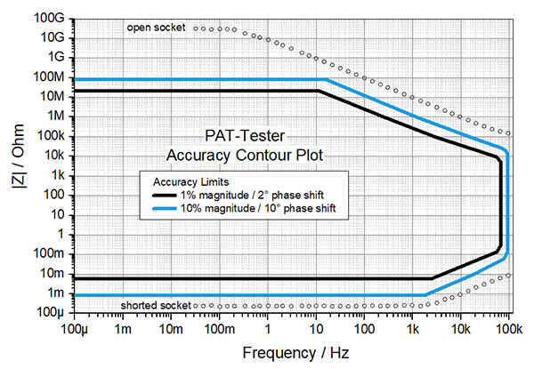
Accuracy Contour Plot
General
# Channels per device 1 to 8 Voltage -7 V to +7 V Current ±100 mA Cell connection / Electrode connection 3 electrodes plus sense wires, switch matrix ADC 2 x 24 Bit DAC 1 x 18 Bit Bandwidth ranges (Stability Factor) 500 kHz (fast) 50 kHz (medium) 5 kHz (slow) Acquisition Time (Time Base) 1 ms Internal Sample Buffer 100 GByte Computer Interface 1 GBit Ethernet Runs standalone Multiuser Voltage
Acquisition of ... Full cell voltage Both half cell voltages Auxiliary voltage Measurement Accuracy ±0.02% of FSR Control Resolution 57 μV (18 Bit) Current
Current Ranges ±100 mA ±10 mA ±1 mA ±100 μA Autorange Measurement Noise floor <1 μA @ 100mA <100 nA @ 10mA <10 nA @ 1mA <1 nA @ 100μA Measurement Accuracy ±0.05% of FSR Control Resolution 1 nA min. (18 Bit) Impedance (each channel)
Frequency range 100 μHz to 100 kHz Impedance mode PEIS and GEIS (simultaneous measurement of full- and half-cell impedances Impedance range 1 mΩ to 100 MΩ


